
Reading Connector Voltage Ratings and Dielectric Test Specifications
Table of Contents
A connector document may contain several electrical numbers expressed in volts. They do not all describe the voltage permitted during normal operation. Rated voltage and a dielectric-withstand test serve different purposes, while insulation resistance is a resistance measurement under defined conditions.
Keep those entries in separate fields when reviewing a cable assembly. A large withstand value should not become the operating limit, and a routine continuity result should not become evidence that either insulation requirement has been met.
Keep operating ratings and insulation-test statements in separate fields
JST PH catalog page 1 gives the three displayed values. The withstand value is a test statement, not an operating rating. A complete test method and exact configuration still require review.
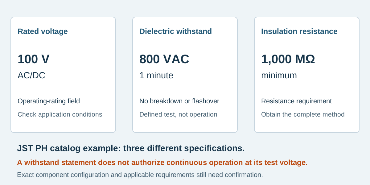
Conceptual illustration. Fictional examples are not approved product configurations, tooling instructions or inspection results.
Read the label attached to the number
Scroll sideways to read all columns.
| Specification | Question it addresses | Information that must stay attached |
|---|---|---|
| Rated voltage | What operating-voltage rating is stated for this component configuration? | AC/DC designation, exact product and applicable conditions |
| Dielectric withstand | Does the defined insulation withstand the specified test without the stated failure? | Test voltage, waveform, duration, connections and acceptance criterion |
| Insulation resistance | What resistance is measured between the specified isolated points? | Measurement voltage, duration or stabilization condition, environment and minimum resistance |
These are related insulation questions, but none is a conversion formula for the others. A resistance limit in megohms is not a voltage rating. A short-duration test at one voltage does not establish continuous operation at that voltage.
The connector current-rating guide addresses loading and temperature rise. Increasing conductor size to address current does not automatically change a connector's voltage rating or its insulating geometry.
A documented PH catalog example
The JST PH catalog, page 1, lists three distinct entries: a 100 V AC/DC voltage rating; insulation resistance of at least 1,000 MΩ; and withstand of 800 VAC for one minute without breakdown or flashover. These values illustrate how the manufacturer separates the fields. They are not three interchangeable descriptions of an 800 V connector.
That catalog also warns that specifications registered to overseas standards can differ from the general specifications. Obtain the applicable exact-part and registration information when the equipment requires it. A family catalog is a starting reference, not the complete approval file for every contact, housing, mate and application.
The summary does not supply every detail needed to reproduce a test. In particular, do not invent the insulation-resistance measurement voltage or the complete terminal grouping from the three headline values. Request the applicable product specification or manufacturer clarification. Copying “1,000 MΩ” without its method leaves a test requirement incomplete.
Define the actual voltage relationships
An equipment description such as “48 V system” may not specify the largest potential difference across every insulating boundary. The responsible designer should identify the normal operating range, any relevant transients, circuit-to-circuit relationships and circuit-to-accessible-metal relationships for the intended installation.
Record AC or DC and the meaning of a stated AC value rather than silently changing between RMS and peak. Define the environmental and installation conditions relevant to the design, including contamination or moisture exposure and altitude where applicable. The equipment's insulation and compliance assessment determines which conditions matter and how they are evaluated; a purchasing checklist cannot approve them by itself.
Avoid setting a generic “safe voltage” from connector pitch. Pitch measures contact spacing in a defined direction; it does not capture every air path, surface path, material property or surrounding feature in the finished equipment. Creepage and clearance need the actual geometry and applicable design requirements.
Keep operating review and production test planning separate
EX-VR-32 is a fictional review record for a proposed 48 VDC assembly. The example deliberately leaves unresolved fields visible rather than inventing limits.
Scroll sideways to read all columns.
| Record field | Example entry | Required next action |
|---|---|---|
| System description | Nominal 48 VDC | Design owner supplies maximum continuous and transient conditions |
| Proposed connector basis | Named contact, housing and mate; specification revision required | Confirm the rating applies to that exact set |
| Ordinary wiring checks | Approved connection map and limits | Agree final harness test coverage |
| Additional withstand request | Customer asks whether one is necessary | Responsible engineering team defines purpose and applicable requirement |
| Test groups and connected parts | Not yet defined | Identify isolated nets, shield and any embedded components |
| Acceptance and records | Not yet approved | Agree method, limits, frequency and evidence before quotation release |
The presence of “48 VDC” does not settle the final selection. Nor does the PH example above authorize a test voltage for EX-VR-32. The useful output is a list of specific decisions with owners.
When an assembly contains components such as LEDs, suppression devices or resistors, make their identity and connections visible before any insulation test is specified. The test arrangement must be suitable for the complete assembly. Do not instruct a factory to connect every circuit together or apply a catalog withstand number indiscriminately.
Ask what evidence the supplier can actually provide
Distinguish component qualification data from production inspection of a delivered harness. A manufacturer report can support a component selection under its stated conditions. It is not a record that the finished harness was tested, and a factory pass label needs a traceable test definition to be meaningful.
For any additional insulation test, agree the exact assembly revision, points or groups, voltage and waveform, timing, acceptance criteria, frequency and requested output. The qualified party developing the method should resolve instrument suitability, handling and discharge requirements. This guide is for specifying a review, not a procedure for applying high voltage to a cable.
Zeakka's established routine scope is continuity and short-circuit checks on each finished cable assembly, with pull-force testing sampled. Additional insulation-resistance or dielectric-withstand testing requires explicit project capability and method confirmation. See what cable assembly test results establish.
Voltage specification questions
Can an 800 VAC withstand connector operate at 800 VAC?
That conclusion does not follow from a withstand statement. Use the rated-voltage specification and the complete application review; preserve the test value as a separate requirement.
Does a continuity and short-circuit pass prove insulation resistance?
No. It establishes the results of the defined wiring checks. An insulation-resistance requirement needs its own conditions and evidence.
Can a compatible connector use the original manufacturer's rating?
Not simply because it fits. The proposed alternative requires evidence for its own materials, construction and mating configuration.
Send the electrical requirements with the assembly drawing
For custom cable assemblies, provide the exact interface references, operating-voltage relationships and any customer-mandated test requirements. Identify unresolved fields instead of substituting a familiar catalog number. Contact Zeakka to coordinate supplier clarification and an agreed quotation scope; equipment-level electrical suitability remains part of the responsible design review.
Share this article
Help others discover this content