
Quick-Disconnect Tabs: Specify Both Width and Thickness
Table of Contents
A request for a “6.35 mm female terminal” leaves an essential dimension unresolved: the thickness of the mating tab. A receptacle intended for one blade thickness should not be assumed suitable for another just because the blade has the same width.
For a quick-disconnect lead, specify the equipment-side tab and the wire-side receptacle as one interface. Then check the wire, insulation or housing, orientation and space required to connect and disconnect it. A familiar width is a useful search filter, not a complete mating specification.
Keep tab width and tab thickness as separate interface fields
Conceptual tab views; dimensions in the comparison are the published mating requirements of two different TE receptacles. Neither row approves a specific tab pairing.
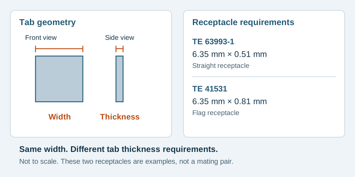
Conceptual illustration. Fictional examples are not approved product configurations, tooling instructions or inspection results.
Distinguish mating dimensions from terminal material thickness
The tab is the blade entering the receptacle. Its mating width and thickness describe that interface. A receptacle's own sheet-metal thickness is a different characteristic and must not be copied into the mating-tab field.
Read the labels alongside the numbers. A catalog may list product length, material thickness, mating width and compatible insulation diameter together. They are not interchangeable dimensions. The connector component guide explains the broader roles of contacts and housings; this guide focuses on specifying a blade-and-receptacle interface.
Two manufacturer examples with the same width
TE's product pages show why width alone is insufficient:
Scroll sideways to read all columns.
| Exact receptacle reference | Listed mating tab width | Listed mating tab thickness | Listed wire range | Orientation and crimp type |
|---|---|---|---|---|
| TE 63993-1 | 6.35 mm | 0.51 mm | 18–14 AWG | Straight; F-Crimp |
| TE 41531 | 6.35 mm | 0.81 mm | 18–12 AWG | Flag; Tab-Lok |
Both references are receptacles. They do not mate with each other, and the table does not approve a tab part number. It demonstrates two distinct requirements hidden by the phrase “6.35 mm.” The differences in orientation and termination also mean that these are not a controlled one-variable substitution comparison.
For an actual design, obtain the selected receptacle's product drawing and applicable application specification, plus the tab drawing or equipment interface specification. Confirm an allowed mating combination through that documentation or manufacturer confirmation. A distributor's similar-products suggestion is not pairing evidence.
Record both sides before selecting a substitute
Use a paired record rather than two independent purchase descriptions. If the equipment already contains the tab, ask for the equipment model, terminal designation and controlled interface data. A measurement can help identify an unknown part but cannot establish its tolerances, plating or qualification.
Scroll sideways to read all columns.
| Interface field | Evidence to capture | Why it changes the review |
|---|---|---|
| Tab identity | Part number or controlled equipment drawing and revision | Defines which blade will actually be present |
| Width and thickness | Both dimensions with the drawing's limits | Prevents a width-only match |
| Engagement geometry | Relevant length, lead-in and retention features | Determines more than whether the tip enters |
| Receptacle identity | Full reference and applicable specification | Preserves the selected contact design |
| Wire applicability | Conductor construction, size and insulation diameter | Checks the wire end independently of the mating end |
| Protection and access | Approved cover or housing, exit direction and service route | Includes the complete installed assembly |
Keep manufacturer units and tolerances clear. Do not silently round a dimensional requirement into a different nominal size, or assume that a near measurement proves identity. Likewise, a blade that can be pushed into a receptacle is not evidence of acceptable contact performance or retention.
A fictional mismatch that the table exposes
EX-QD-23 is an invented sourcing review. Equipment drawing E-23 identifies a tab with nominal width 6.35 mm and nominal thickness 0.81 mm. The drawing's actual limits and full interface details must accompany the RFQ; these two nominal values alone do not approve a connection.
An initial quotation proposes TE 63993-1 because the width matches. Its published mating-tab thickness is 0.51 mm, so that proposal does not satisfy the stated 0.81 mm requirement. Record the discrepancy and request a corrected proposal. Do not spread, flatten or otherwise modify the receptacle to make a sample fit.
TE 41531 has a matching listed width and thickness, but that only advances it to further review. Its flag orientation may conflict with the enclosure, its wire-side applicability still needs checking, and the specific tab pairing remains unconfirmed. Mark the row “candidate; not approved” until those open questions are resolved. This avoids replacing one incomplete decision with another.
Check the wire, cover and service motion
The chosen wire must meet the exact receptacle's requirements, including its insulation support where applicable. Gauge alone does not define insulation diameter or conductor construction. Ask the proposed manufacturer to identify the relevant preparation, tooling and inspection requirements for the actual combination; do not transfer a strip length or crimp setup from another terminal of similar width.
Straight and flag constructions place the wire differently relative to the tab. Include the complete receptacle, insulation cover or housing and wire bend in the enclosure review. Reserve an unobstructed connection path and the access needed for the specified disconnection method. Pulling on a cable is not a substitute for the selected system's removal instructions.
A generic sleeve must not be assumed to fit every receptacle or provide a particular safety classification. Select any cover or housing from applicable documentation and check that it does not prevent full engagement or required release access. A locking feature, if present, must be identified specifically rather than inferred from the word “quick.”
Define what sample review must establish
Keep dimensional screening, wire termination inspection and system testing distinct. A dimensional match does not assign a current rating or operating temperature to the complete cable. Obtain applicable ratings and conditions for the selected parts, wire and installation, then agree the necessary evidence for the intended application.
In the sample record, preserve tab and receptacle identities, wire specification, assembly revision and the actual mating fixture. Record the required engagement or retention checks against the applicable method and limits. Avoid inventing a universal insertion force, pull force or reuse count for all quick-disconnect terminals.
Quick-disconnect questions
Does “250 series” fully specify the mating tab?
No. Keep the actual width, thickness, interface geometry and exact references. The examples above share a nominal width while specifying different tab thicknesses.
Can I use the receptacle's material thickness as the tab thickness?
No. They describe different parts of the construction. Read the field explicitly labeled for the mating tab and verify the drawing.
Does a matching width and thickness approve an alternative brand?
No. Confirm the complete proposed interface and its evidence. The original manufacturer's requirements and qualification do not automatically transfer to another supplier's product.
Request a paired-interface review
Send Zeakka your discrete-wire cable requirements, including the tab drawing or equipment reference, proposed receptacle, wire specification, cover or housing, orientation, quantities and required verification. Zeakka acts as a sourcing and trading partner. Availability and suitability of a specific construction remain subject to project review; this guide does not establish a stock range or an approved interchangeable terminal list.
Share this article
Help others discover this content