
Wire Harness Assembly Boards: Turning a Layout into Repeatable Fixture Inputs
Table of Contents
A wire harness assembly board provides defined locations for holding and arranging a harness during assembly. To make that arrangement repeatable, the board needs controlled inputs: where connector datums sit, how each housing is oriented, where branches separate and which instructions belong to that setup revision.
The board should follow an approved harness definition. It should not silently become the source of missing installation dimensions or a substitute for checking the harness in its equipment. Three different descriptions must stay connected: the installed three-dimensional route, the assembly-board layout and the wire preparation data.
Keep the board coordinates tied to the installed route
Fictional EX-AB-07: N1 at 0,0; branch G1 at 180,0; N2 at 340,0; N3 at 180,120 millimeters. Locators do not define wire cut lengths or approved bends. X increases right and Y upward.
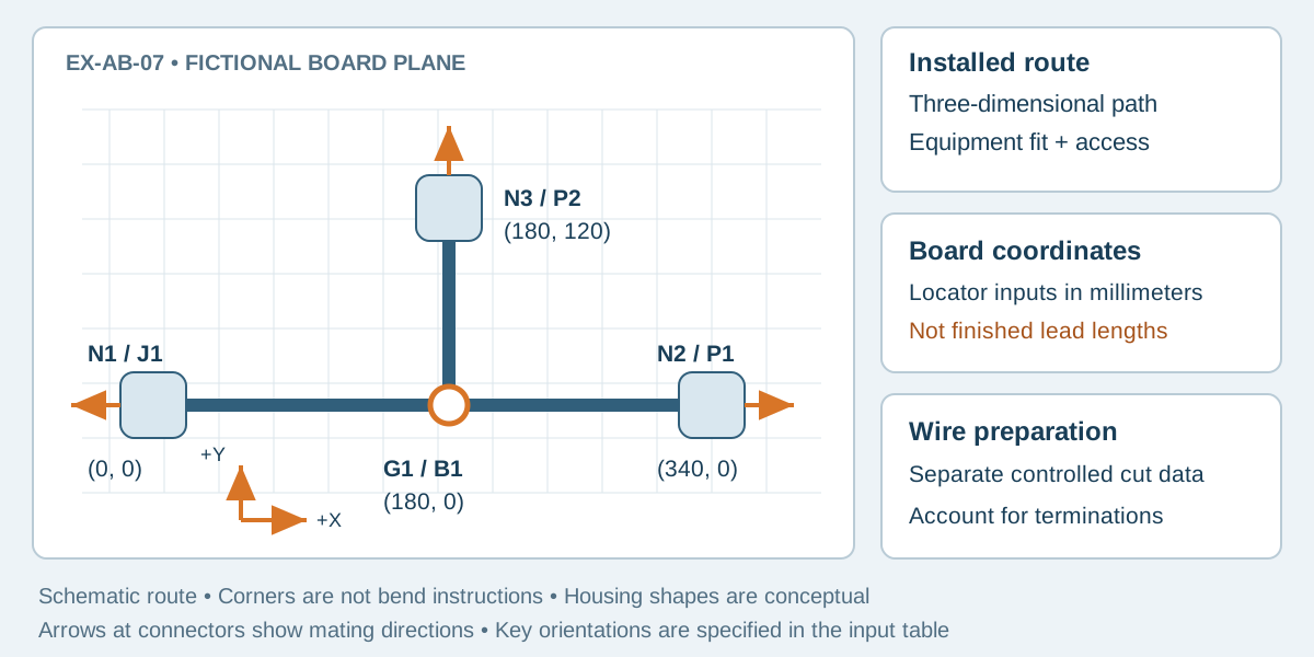
Conceptual illustration. Fictional examples are not approved product configurations, tooling instructions or inspection results.
Separate the installed route from the board layout
An installed harness may turn around brackets, rise between levels and leave space for access or movement. A board may arrange portions of that harness in a convenient plane. Projecting the installed route onto that plane does not preserve every path length, bend or connector orientation automatically.
Identify which dimensions represent finished harness requirements and which coordinates locate tooling. A locator coordinate can position a connector nest without specifying the wire's cut length. Wire preparation also depends on the actual termination, routing method and allowances approved for that assembly.
The length and tolerance guide explains how to define finished measurement endpoints. Here the next question is how a fixture references those endpoints consistently while allowing the harness to be assembled and removed.
Define what the board is expected to do
Panduit's wire harness application page describes its Quick-Build system as reusable grid tiles and mounting pegs used for routing and forming wires. That provides a concrete example of a configurable assembly-board approach. The manufacturer's product description does not establish the correct locator positions, bend controls or acceptance criteria for a particular harness.
Before choosing tooling, state the operations the proposed board supports. These might include locating connector housings, arranging identified wire groups or controlling where specified wrapping starts and stops. Review tooling contact with the actual parts, access for the planned operations and the removal path for the completed assembly.
An assembly board is not automatically an electrical test fixture. If a design combines mechanical holding and electrical test connections, the test interface, circuit coverage and acceptance logic need their own controlled definition. A harness fitting the board does not demonstrate correct pin mapping or electrical isolation.
Build a locator input table
Use stable identifiers for the connector nests, branch guides and reference features. Tie each one to an assembly drawing revision. Define the board origin, axis directions, units and the datum on each part that the fixture locates.
Scroll sideways to read all columns.
| Input | Decision to record | Why it matters |
|---|---|---|
| Assembly and fixture revision | Drawing revision and matching board setup identifier | Prevents an old layout from building a revised harness |
| Origin and axes | Physical reference, X/Y direction and units | Makes coordinates reproducible |
| Connector nests | Located datum, housing identity and orientation | Prevents a mirrored or rotated assembly |
| Branch guides | Branch identifier and controlled routing relationship | Distinguishes similar outgoing legs |
| Height or off-plane features | Required support height and separate view where needed | Avoids flattening a three-dimensional requirement |
| Process boundaries | Defined wrapping, protection or label locations | Keeps fixture marks tied to actual drawing requirements |
| Setup verification | What is checked and against which revision | Separates fixture approval from visual familiarity |
Record positioning tolerances and the method used to verify them in the real fixture documentation. Do not borrow a tolerance from a board grid spacing or from a different harness. If two locators constrain the same dimension, check that they do not force the assembly into position under unwanted tension.
A fictional board-input example
The following EX-AB-07 layout is a teaching example, not a manufacturing release. Coordinates are millimeters in a fictional board plane, with X increasing right and Y increasing upward. Connector nests locate named mating-face center datums. Housing outlines are conceptual and do not represent orderable parts.
Scroll sideways to read all columns.
| Locator | X | Y | Located item and orientation input |
|---|---|---|---|
| N1 | 0 | 0 | J1 mating-face center; mating direction left; key reference toward +Y |
| G1 | 180 | 0 | B1 branch reference; main route arrives from N1 |
| N2 | 340 | 0 | P1 mating-face center; mating direction right; key reference toward +Y |
| N3 | 180 | 120 | P2 mating-face center; mating direction up; key reference toward +X |
These coordinates give a fixture-layout concept. They do not prescribe connector nest geometry, routing radii, tolerances, finished lead lengths or raw wire cut lengths. The route drawn through G1 is schematic; its corner is not a zero-radius bending instruction. A released setup would replace these simplifications with defined guides and approved transitions.
In this example, the coordinate difference between N1 and G1 is 180 mm in X. That does not authorize cutting a wire to 180 mm. Likewise, N3's 120 mm Y offset does not establish its finished branch length. The physical path, connector datums and preparation requirements still need their own definitions.
Pair the layout with the approved circuit table and branch identification. The board can label an outgoing leg P2, but its label cannot establish which individual wire belongs in P2's cavities. Keep that mapping in the controlled assembly documentation described in the drawing preparation guide.
Verify the setup and the first assembled harness separately
First check the empty setup: fixture identity, origin, locator positions, orientation features and current instructions. Confirm that any replaceable or adjustable elements are set and secured as required. The review should establish what was checked rather than merely photograph a board with a harness on it.
Then assess the assembled harness against its own requirements. Confirm connector orientation, branch identity, finished dimensions and specified protection locations. Remove it without forcing parts or snagging wires, and evaluate it in the intended equipment or an agreed representative installation.
Do not compensate for an unexplained installation problem by moving a locator until one sample fits. Identify whether the assembly definition, fixture setup, preparation data or installation assumption needs correction. Update the affected controlled records and repeat the relevant checks.
Keep changes traceable
A new connector body, branch position or protective sleeve can affect access and locator geometry even when the circuit table is unchanged. Conversely, a wiring revision may leave the mechanical board unchanged while requiring new electrical checks.
Record what changed, which fixture elements were affected and which sample checks were repeated. If the layout is printed at full size, verify its scale against defined reference dimensions before use. A print setting such as “fit to page” must not become an unnoticed fixture adjustment.
Frequently asked questions
Can the board layout replace the installation drawing?
No. It describes the assembly setup. The installed route may include three-dimensional features or movement that the flat layout does not show.
Does the board determine wire cut lengths?
Not by coordinates alone. Cut data must account for the controlled path and actual terminations, and be confirmed against the finished assembly requirements.
Does a harness that fits the board pass inspection?
Fit is only one observation. Required dimensional, visual and electrical checks remain separate, as does confirmation in the intended installation.
Send the route and fixture inputs together
For custom discrete-wire cable assemblies, contact Zeakka with the approved harness drawing, installation references, locator table and revision status. Identify whether a board already exists and which party owns its design and approval. Zeakka coordinates sourcing as a trading partner; assembly-board arrangements and requested verification evidence require project-specific confirmation.
Share this article
Help others discover this content