
Routing Pre-Terminated Harnesses Through Enclosure Openings
Table of Contents
A pre-terminated harness can meet its drawing and still be impossible to install through the intended enclosure opening. The cable fits, but the connector housing, latch, boot or branch does not. Discovering this after assembly creates a choice between changing the equipment and changing an already controlled harness.
Review the passage with the harness in its delivered condition. Define what crosses the panel, which orientation is permitted and what remains in the way throughout the movement. A larger hole is only one possible solution, and its effect on panel strength, protection and sealing needs separate approval.
Check the complete passage, including the next obstruction
Fictional EX-ENTRY-29 geometry in millimetres. The frontal clearance calculation assumes a straight aligned passage and square opening corners. The second bracket blocks that straight route; the sketch is not to scale.
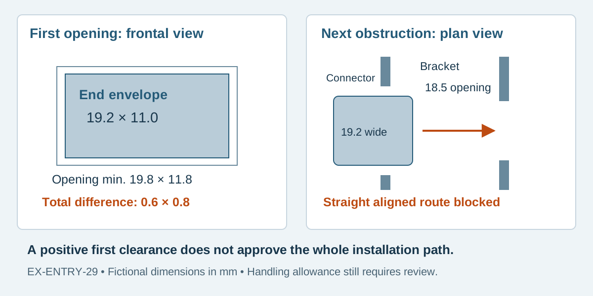
Conceptual illustration. Fictional examples are not approved product configurations, tooling instructions or inspection results.
Start with the item that actually has to pass
Record the complete end configuration: housing, populated contacts, locks, seals, boot, sleeve, label and any protective cap that must remain fitted. A housing drawing alone may omit the feature that controls passage. If temporary packaging is removed before installation, state that step explicitly; a functional secondary lock is not packaging.
For a branched harness, identify which end enters first and whether another branch has to follow through the same opening. A cable that passes before a branch reaches the panel may become trapped when the junction arrives. The installed cable diameter describes the final state, not every intermediate state.
Scroll sideways to read all columns.
| Passage input | Required definition | Common omission |
|---|---|---|
| Connector end | Maximum complete envelope in the permitted orientation | Latch, boot or cap excluded |
| Opening | Minimum usable shape after specified finishing and installed edge protection | Nominal machining size used alone |
| Panel region | Thickness, adjacent walls and any second opening | Only the front face shown |
| Cable behind the end | Exit direction, permitted bend and nearest branch | Cable treated as a flexible line with no size |
| Assembly state | Which panels and brackets are fitted at that step | Access available only in an earlier build stage |
The vertical versus right-angle header guide addresses access for mating a connector to a PCB. Passing a disconnected cable end through a wall is a different motion and needs its own section view.
Compare minimum opening with maximum envelope
For a defined straight, aligned passage through a rectangular opening, compare its minimum usable width and height with the maximum projected width and height of the complete end. Keep the drawing tolerances in the calculation. Subtracting nominal values can hide interference at the production extremes.
The result is total geometric clearance across each dimension. It is not automatically clearance on each side, and it does not establish the allowance needed for handling, misalignment, edge protection or a nonrectangular feature. Rounded opening corners also matter: a rectangular envelope can satisfy width and height while its corners intersect the actual opening.
Do not use the diagonal of a rectangular hole as proof that a connector fits when rotated. Rotation changes both projected dimensions and the space swept by the cable exit. Review the actual outline and path in CAD or a controlled physical trial when the passage depends on rotation.
A fictional straight-passage check
EX-ENTRY-29 is a simplified enclosure review, not a product specification. Assume a rectangular usable opening with square corners for this calculation, a straight aligned passage and a connector end whose stated maximum envelope already includes its latch. All dimensions are millimetres.
Scroll sideways to read all columns.
| Quantity | Drawing input | Value used in the limiting check |
|---|---|---|
| Usable opening width | 20.0 ± 0.2 | 19.8 minimum |
| Usable opening height | 12.0 ± 0.2 | 11.8 minimum |
| Complete connector width | Maximum envelope | 19.2 maximum |
| Complete connector height | Maximum envelope | 11.0 maximum |
| Width difference | 19.8 − 19.2 | 0.6 total |
| Height difference | 11.8 − 11.0 | 0.8 total |
If perfectly centred, these differences correspond to 0.3 mm per side horizontally and 0.4 mm vertically. That observation does not approve the clearance for installation. The project has not yet established handling allowance, alignment variation or the effect of the trailing wire bundle.
Now add a fixed internal bracket behind the panel with an 18.5 mm-wide opening. The same straight, aligned 19.2 mm-wide connector cannot continue through it. The first opening's positive clearance does not resolve this second obstruction. If another route is proposed, review that route explicitly rather than marking the original path “pass.”
Resolve the route before modifying the harness
Possible design responses include changing the approved opening, moving the obstructing bracket, using a removable panel, specifying a suitable split entry system or changing where final termination occurs. Each response changes a different responsibility.
icotek's split cable gland overview documents entry systems that assemble around pre-terminated cables. This establishes that such an architecture exists; it does not make any particular system suitable for the fictional opening or imply that Zeakka supplies it. Its complete mounting geometry, cable applicability and installation requirements must be checked. The connector still needs an approved route through the enclosure boundary.
If contacts are to be inserted into a housing after passage, that is a defined assembly operation. Assign its instructions, tooling where applicable, terminal retention checks, cavity mapping and final electrical verification. Do not authorize informal depinning, trimming a latch or cutting a finished cable to make it fit. The connector depinning guide addresses controlled rework separately.
Record installation evidence at the right stage
A useful trial records the harness revision, enclosure revision, installed obstructions, passage direction and the exact configuration tested. Photographs should show both sides of the wall and the complete route. Note any cap removal or temporary support used; otherwise the next build may repeat the trial with different assumptions.
After passage, inspect the affected housing, contact retention features, insulation and protection as required by the agreed process. Confirm the final route and restraint. A successful transit does not demonstrate sealing or strain relief. Those are the panel-entry functions discussed in the glands and grommets guide.
Enclosure passage questions
Can I size the opening from cable diameter?
Only when the installation state genuinely requires the cable alone to pass. For a connectorized end, use its complete passage envelope and the route behind it.
Does passing one sample prove production clearance?
It demonstrates that sample and enclosure under the recorded conditions. Compare the controlled tolerances and intended assembly method before accepting the design for repeated builds.
Can a removable latch or terminal solve the problem?
Only through an approved assembly or rework process for the exact parts. A feature should not be removed simply because it obstructs the opening.
Send the passage drawing with the harness RFQ
For custom discrete-wire cable assemblies, include the delivered end configuration, minimum usable opening, panel section, fixed obstructions and intended sequence. Mark whether the request is for a finished harness or includes later customer assembly. Contact Zeakka to coordinate supplier review of the proposed scope; enclosure suitability and any changed installation process need approval from the responsible project team.
Share this article
Help others discover this content