
Cable Glands vs Grommets: Defining the Panel Entry
Table of Contents
A cable passing through a panel creates several separate jobs: protecting the cable from the edge, retaining it against the intended loads and controlling any required ingress path. A grommet or cable gland should be chosen by the jobs its exact design is documented to perform.
The useful starting point is a panel-entry definition: opening geometry, panel thickness, actual cable outside diameter, installation sequence and required performance. “Fit a rubber grommet” or “use an M20 gland” leaves too much unresolved for a finished assembly.
Define the cable-to-panel interface before selecting hardware
Conceptual cutaway views show an edge-protection grommet and a compressing cable gland at a panel. Cable diameter, panel thickness, opening geometry and the panel sealing interface are separate review inputs.
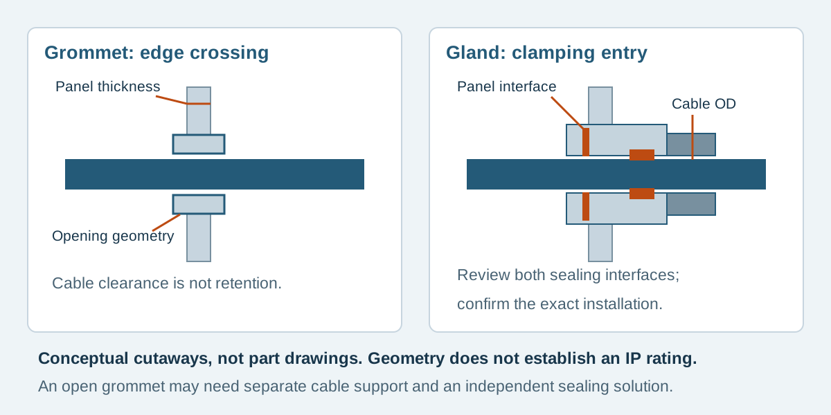
Conceptual illustration. Fictional examples are not approved product configurations, tooling instructions or inspection results.
Assign each function before choosing a part
A conventional open grommet can cover the edge of an opening while leaving clearance around the cable. That clearance is not cable retention or a verified seal. Some specialized grommets have additional functions, but those belong to the selected design and installation.
A compression cable gland may combine cable clamping and sealing, with a separate interface where its body enters the panel. Check the exact product and its mounting instructions. A gland-shaped part, a compression nut or a catalog ingress rating does not by itself demonstrate the performance of the assembled enclosure.
Scroll sideways to read all columns.
| Requirement | Question to resolve | Evidence to request |
|---|---|---|
| Edge protection | Is the cable isolated from the prepared panel edge? | Selected geometry and installed inspection |
| Cable retention | Which feature carries the specified cable load? | Applicable retention requirement and verification |
| Cable-side sealing | Does the insert suit the cable's actual profile and diameter? | Product applicability and installation requirements |
| Panel-side sealing | How is the body-to-panel path controlled? | Correct mounting arrangement and sealing components |
| Service access | Can the cable and hardware be removed in the installed state? | Assembly sequence and access review |
The strain-relief guide discusses load paths and bending. This guide narrows the review to the cable-to-panel interface. Sleeving along a harness is a further decision covered in the wire harness protection guide.
Use separate dimensions for the cable, opening and panel
The cable's outside diameter is not the panel-hole diameter, and a gland's thread designation is not a complete hole drawing. Record cable diameter with its applicable tolerance and profile; an oval or irregular bundle is not automatically equivalent to a round jacketed cable of the same maximum width.
For a grommet, check the specified mounting hole, panel thickness and inside opening. Include hole shape, preparation and any required edge condition. For a threaded gland, establish whether the body enters a tapped hole or passes through a clearance hole secured by a locknut. Obtain the manufacturer's mounting dimensions and define any panel seal separately.
Panel thickness also affects available thread engagement and the space for a locknut or sealing stack. Thread length is not automatically the maximum permitted panel thickness. Do not release a clearance hole from the thread name alone or derive an installation torque from a similar-looking part.
Two documented parts illustrate different checks
The Heyco thick-panel grommet table lists G1086 under the 0.250 inch (6.4 mm) panel section. Its listed mounting hole is 0.500 inch (12.7 mm), and its inside diameter is 0.31 inch (8.0 mm). These are different dimensions serving different purposes. The row identifies nitrile material; it does not supply a cable-clamping range or establish a sealed cable entry.
For a different construction, the LAPP SKINTOP ST-M table lists article 53111020 with an M20×1.5 thread, a 6–13 mm cable clamping range and a 9 mm thread length. Those values belong to that article. The thread designation and length still do not define every panel-mounting detail.
These are document-reading examples, not equivalent alternatives or confirmed Zeakka supply items. Obtain the current applicable part drawing and installation instructions before design release; do not transfer dimensions to another suffix, reduced-range insert or substitute product.
A fictional panel-entry screening exercise
EX-PE-26 is an invented enclosure review with a round jacketed cable specified at 7.0 ± 0.2 mm outside diameter. The panel is nominally 6.4 mm thick; its manufacturing tolerance remains unresolved. The customer is comparing edge protection with a retained entry, so the opening has not yet been released.
Scroll sideways to read all columns.
| Screening item | G1086 grommet candidate | 53111020 gland candidate |
|---|---|---|
| Cable interval | 6.8–7.2 mm compared with listed 8.0 mm inside diameter | 6.8–7.2 mm lies within listed 6–13 mm clamping range |
| Panel | Nominal value matches the table section; tolerance and fit still need review | Mounting stack and engagement remain unresolved |
| Opening | Candidate table lists 12.7 mm mounting hole; obtain applicable tolerance | Obtain tapped or clearance-hole drawing for chosen mounting method |
| Retention | Not established by this dimensional comparison | Confirm applicability and installed performance |
| Sealing | Not established | Confirm both cable and panel interfaces |
For the grommet, the simple diameter difference between an 8.0 mm nominal opening and the largest stated cable is 0.8 mm. This is only nominal dimensional screening; it is not an interference fit, retention result or sealing calculation. Grommet tolerances and deformation have not been evaluated.
For the gland, falling within the clamping range is a useful first screen. It does not settle jacket compatibility, mounting stack, tightening requirements or enclosure performance. The example deliberately does not divide the 9 mm thread length into an invented permitted panel thickness and locknut allowance.
Choose the required functions first, then resolve the remaining fields. If the application needs only edge protection plus a separate internal cable support, document both components. If it needs a sealed retained entry, require the relevant evidence for that complete installed arrangement.
Plan how the terminated cable reaches its final position
Before approving either approach, walk through installation with the connector envelope included. A closed grommet, gland nut or sealing insert may need to slide onto the cable before termination. A connector may clear the panel opening while failing to pass through one of the loose hardware pieces.
Record which parts are fitted before termination, which remain loose for enclosure installation and who performs the final tightening. If selecting a split design for a preterminated cable, verify its exact assembly method and performance instead of assuming every grommet or gland can be split.
Allow access for the specified tools, locknut and cable bend. Identify the service procedure as well as initial assembly. A cable that can be installed only before a large internal component is fitted needs that sequence recorded in the equipment instructions.
Frequently asked questions
Is a grommet automatically a strain relief?
No. Establish whether the selected part provides the required retention. An open edge-protection grommet may need a separate support to transfer cable loads into the enclosure.
Does M20 mean the panel needs an exactly 20 mm clearance hole?
It identifies a thread size, not a complete mounting specification. Use the applicable product drawing for the selected tapped or clearance-hole arrangement and define tolerances and sealing details.
Can a gland's catalog IP rating be applied to the whole enclosure?
Do not infer enclosure performance from the component label alone. Confirm the cable, panel interface, mounting components and installation conditions, then obtain the verification required for the assembled configuration.
Send the panel interface with the cable assembly RFQ
For cable assemblies, include the cable specification and diameter tolerance, panel drawing, desired entry functions, connector envelope and installation responsibilities. Mark any proposed gland or grommet as a candidate until its mounting details are resolved. Zeakka coordinates sourcing as a trading partner; exact hardware availability and the proposed assembly and verification scope require confirmation. Contact Zeakka with the interface drawing so those items can be reviewed with the quotation.
Share this article
Help others discover this content