
Contact Resistance vs Cable Loop Resistance: Defining the Measurement Boundary
Table of Contents
“The resistance is too high” is incomplete until the measurement boundary is clear. A connector contact specification and a reading through an entire harness may describe different objects. Both can be expressed in milliohms while including different wires, terminations and fixture connections.
Start by drawing the current path and labeling the voltage-sense points. Then agree the method and acceptance criterion for that path. Changing from two-wire to four-wire measurement can improve a measurement without changing which assembly elements it includes.
Define the resistance measurement boundary
Anything between the selected sense points remains part of the measured path.
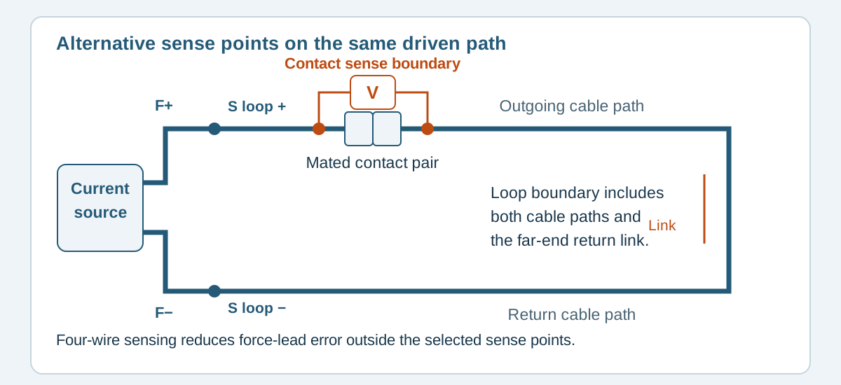
Conceptual illustration. It does not depict an approved product configuration or test result.
Name the object being measured
Contact resistance concerns a closed mating contact pair under a specified method. A practical connector specification may define test points that also include portions of the terminals or attached conductors. Check that method before interpreting a catalog number as resistance at the microscopic interface alone.
A cable path measurement may include wire, crimped terminations, mated connectors and splices. A loop measurement adds a return route and whatever connection closes the far end. In a branched harness, the return may be shared, so the loop is not automatically twice one conductor's resistance.
Scroll sideways to read all columns.
| Intended result | Boundary to mark | Easily overlooked contribution |
|---|---|---|
| Specified connector contact result | Product test points on each side of the selected mate | Terminal body or wire segments required by the method |
| One assembly circuit | Named endpoints on a drawing | Both terminations and any intermediate joint |
| Outbound and return loop | Near-end endpoints and the complete far-end return connection | Return conductor, jumper and its joints |
| Fixture-inclusive troubleshooting result | Instrument connection points through the fixture and specimen | Adapters, switching paths and worn mating contacts |
Keithley's switching handbook explains closed-contact resistance measurements and shows separate source and sense switching to keep unwanted test-path contributions out of the reading. The fixture topology therefore belongs in the method, alongside the instrument setting. Keithley switching handbook, printed page 11
Separate instrument leads from the chosen boundary
With a two-wire connection, the same leads carry test current and provide the measured voltage. Their resistance contributes to the result. With a four-wire, or Kelvin, connection, separate sense leads measure voltage at selected points while force leads supply current. Sense placement is central to reducing lead-related error. Tektronix two-wire and four-wire measurement explanation
Four wires at the instrument do not prove that the measurement excludes the adapter or cable. If the sense wires join the force wires before an adapter, that adapter remains inside the sensed path.
For a conceptual layout, place two alternative boundaries on the same series path:
- A narrow boundary surrounds one specified connector mating pair.
- A wider boundary surrounds the outward wire, far-end return link and return wire, including their terminations.
- The force connections lie outside the selected sense points; the reported resistance corresponds to the voltage between those points divided by test current.
Moving the sense points changes the measured object. Merely selecting a four-wire instrument mode does not isolate a contact buried inside a completed connector. Access and specimen preparation must follow the agreed method.
A fictional loop with several contributions
Consider this illustrative circuit only, using invented values to explain accounting. It is not a product rating, expected result or acceptance limit.
A two-conductor assembly is closed by a far-end return link. Assume a four-wire measurement senses at the two near-end circuit terminals, with the instrument force-lead drops outside those points. Within the boundary, assume:
Scroll sideways to read all columns.
| Included element | Invented contribution |
|---|---|
| Outbound conductor | 8 mΩ |
| Return conductor | 8 mΩ |
| All included terminations and mating connections combined | 6 mΩ |
| Far-end return link and its connections | 3 mΩ |
| Total | 25 mΩ |
The arithmetic is 8 + 8 + 6 + 3 = 25 mΩ. Reporting this as “25 mΩ contact resistance” mislabels the result. Dividing by the number of connector contacts also fails because the wires and link are still included, and the individual contact contributions have not been measured.
A shorter assembly could produce a lower total with unchanged connectors. A changed return adapter could alter the total without a change in either wire. Those possibilities show why supplier comparisons need the same boundary.
Specify conditions before comparing readings
Use an isolated, de-energized specimen under the responsible test procedure. Identify parallel paths or embedded components that would change where current flows. Record the physical connection arrangement rather than relying on a tester file name.
Scroll sideways to read all columns.
| Measurement record | Required detail |
|---|---|
| Specimen | Assembly part, revision, length, unit and mating components |
| Boundary | Labeled force and sense points, with a sketch or photograph |
| Return arrangement | Jumper, return conductor, shared connections and adapters |
| Method | Two-wire or four-wire, instrument, range and procedure revision |
| Electrical conditions | Test current and voltage limits, timing and relevant compensation |
| Physical condition | Temperature, stabilization, mating history and fixture condition |
| Result and criterion | Measured value and units, applicable limit and its source |
| Fixture treatment | Included contributions and the approved correction method, if used |
Low-level contact testing can require limits on both current and voltage to avoid altering the junction being assessed. Keithley discusses this as dry-circuit testing. Use the selected product's required conditions rather than choosing a higher current simply for an easier reading. Keithley handbook, printed page 12
Compare a catalog limit with its own method
The JST PH catalog distinguishes initial contact resistance from resistance after testing. Those are connector specifications, not automatic limits for an arbitrary PH-ended cable loop. Obtain the applicable product specification and measurement details before comparing a completed assembly result. JST PH catalog, page 1
If a drawing calls only for a continuity pass, do not convert that result into a precision contact measurement. The assembly testing guide covers connection maps and continuity limits. Voltage-drop selection belongs to the separate wire-gauge guide.
For custom cable assemblies, attach the measurement sketch and required report to the RFQ checklist. Zeakka coordinates the proposed method with the selected supplier. Precision low-resistance testing requires explicit feasibility agreement; it is not implied by the standard continuity and short-circuit checks.
Common questions
Does four-wire measurement give contact resistance automatically?
No. It reduces lead-related measurement error when connected correctly. Every series element inside the sense points still contributes.
Can I subtract a known wire resistance from a loop result?
Only under an agreed method that accounts for the actual wire, temperature, length and other included elements. Subtraction does not establish the remaining value's uncertainty or identify a particular failed contact.
Is a lower reading always evidence of a better harness?
Only compare results measured on equivalent paths under equivalent conditions and against the intended requirement. A lower total from a shorter cable does not establish better mating contacts.
Share this article
Help others discover this content