
Ring vs Fork Terminals: Specify the Installed Connection
Table of Contents
A ring terminal and a fork terminal may connect a wire to a screw or stud, but they do not create the same installation sequence. A closed ring must pass over the end of the fastener. An open fork can approach from the side if the fastening arrangement permits it. That difference matters when a nut is captive, a cover limits access or a cable must be replaced during service.
Choose the terminal together with the receiving connection, hardware and installation space. A wire size and a nominal screw size are only the beginning of that definition.
Reserve the installation path as well as the terminal footprint
Conceptual ring and open-fork interfaces, not manufacturer drawings. Vertical and lateral access depend on the complete receiving hardware and equipment instructions.
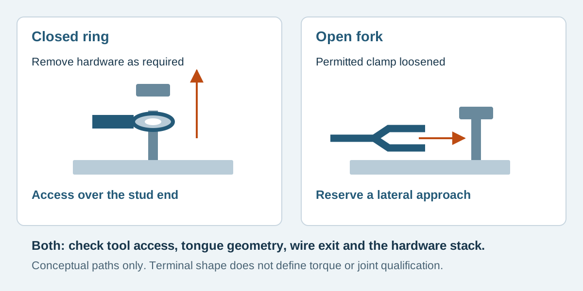
Conceptual illustration. Fictional examples are not approved product configurations, tooling instructions or inspection results.
Compare the installation paths
Here, “fork” means an open spade tongue intended for a screw or stud connection. It does not mean a flat quick-disconnect tab. Those interfaces need a different mating check.
Scroll sideways to read all columns.
| Decision | Closed ring | Open fork or spade |
|---|---|---|
| Getting onto the fastener | Requires access over the fastener end | May enter sideways after loosening the clamp, where permitted |
| Removing the lead | Usually requires removing the relevant nut or screw from the ring's path | May permit withdrawal without removing the fastener completely |
| Space to reserve | Space above the stud plus the tool and cable route | Lateral approach and withdrawal space plus tool access |
| What must remain controlled | Hole, tongue, hardware stack and clamping interface | Slot, tongue style, hardware stack and clamping interface |
| What the outline does not establish | Correct torque, electrical performance or vibration qualification | Correct torque, retention under service conditions or vibration qualification |
A closed ring surrounding a stud does not prove that the joint remains electrically sound when loose. Similarly, convenient fork removal is not evidence that a fork is acceptable for every service environment. Use the equipment manufacturer's connection requirements and the selected terminal's documentation to approve the arrangement.
Name the tongue style and the receiving hardware
“Fork terminal” is not one exact geometry. For example, TE identifies 52420-1 as a spring spade for 16–14 AWG and a #6 / M3.5 stud. TE identifies 130118 as a closed-ring terminal for 16–14 AWG and an M6 stud. These are examples of different catalog identities, not interchangeable alternatives: they share a wire-range label but serve different stud interfaces.
Keep the exact manufacturer and part number in the BOM. Use the product drawing to establish the actual hole or slot geometry, tongue width, thickness and relevant tolerances. Do not treat a nominal screw designation as the terminal's measured clearance dimension. If the fastener size is unknown, a photograph beside a ruler is useful supporting evidence but does not replace its specification.
Identify the receiving part as well. Record the screw or stud, contact surface, permitted terminal type, washer or pressure-plate arrangement, locking hardware and installation instruction. A stack assembled from individually plausible parts may still conflict with the equipment's instructions. Do not invent a universal washer sequence or tightening torque from terminal shape.
Reserve the complete installation envelope
The visible tongue is only one part of the space claim. Include the barrel or insulated neck, wire exit, nearby walls, tool approach and the route needed to install or remove the lead. Check the assembled condition and the service motion separately.
A fork that fits beneath a screw head when loose on the bench may have no sideways access once installed beside a barrier. A ring may fit a stud but leave insufficient vertical room to lift it over the stud during service. Rotating either terminal can change the wire's bend and its proximity to another circuit. Define the intended orientation in a view rather than leaving it to assembly preference.
Insulated barrels also do not necessarily cover the tongue or receiving connection. Where the equipment requires a cover or barrier, identify that part and the resulting access restriction. Do not infer touch protection from insulation color.
A fictional service-access decision
EX-RT-22 is a hypothetical low-voltage equipment layout exercise, not an approved electrical design. Both candidates must ultimately suit the equipment's specified M4 connection and the same selected wire. No orderable terminal is assigned yet.
Scroll sideways to read all columns.
| Review item | Position A | Position B |
|---|---|---|
| Receiving connection | M4 stud with removable nut | Captive M4 screw in a specified clamping assembly |
| Access condition | Clear vertical access after removing the cover | Side wall restricts one approach direction |
| Candidate concept | Closed ring, subject to drawing review | Fork only if the receiving assembly permits it |
| Required evidence | Ring geometry, complete hardware stack and tool clearance | Approved tongue style, lateral insertion route and clamp engagement |
| Decision still open | Actual terminal reference and installed wire route | Whether the fork can be installed and removed within the enclosure |
The useful result is not “rings are better” or “forks are faster.” It is a record of what each location needs. If Position B does not provide a permitted insertion route, redesign that interface or access arrangement; do not trim the fork or force it beneath the clamp.
Once a terminal is selected, define finished lead length using named datums. The cable assembly length guide explains endpoint and tolerance choices. A ring's hole center can be a drawing datum, but it does not establish the space needed around the installed hardware.
Separate wire termination from equipment installation
The cable supplier may crimp the terminal while the equipment assembler makes the screw joint. State who supplies the hardware, who installs the lead and which records each party provides. Otherwise a cable inspection can be mistaken for acceptance of a joint that has not yet been assembled.
For the wire end, review the exact conductor construction, insulation dimensions, terminal applicability and specified tooling. For the installed connection, follow the controlled hardware and installation requirements. Record inspection criteria appropriate to each stage; a passing continuity check alone does not qualify the mechanical joint. The crimp evidence guide covers the wire-side evidence in more detail.
Ring and fork terminal questions
Can I replace a ring with a fork of the same wire size?
Only after reviewing the receiving connection, permitted tongue style, installed geometry and service requirements. The shared wire-size range does not approve the replacement.
Is a spring spade the same as a plain fork?
Do not assume that it is. Preserve the exact tongue style and part reference, and check its drawing and installation requirements. A generic sketch cannot establish the behavior of every spade design.
Should the RFQ include the screw and washer?
It should identify the receiving hardware and installation requirements even when those parts are supplied elsewhere. State whether the quotation includes them so the assembly boundary is clear.
Send the connection detail with the lead drawing
Ask Zeakka to review your discrete-wire assembly request with the terminal references or candidate requirements, receiving connection drawing, wire specification, orientation, finished dimensions and expected quantities. Include photos of restricted access where helpful. Zeakka coordinates sourcing as a trading partner; the feasibility and supply scope of a particular ring or fork construction require project-specific confirmation.
Share this article
Help others discover this content