
Mixed Wire Gauges in One Connector Housing: A Cavity Review
Table of Contents
A connector family can list several wire sizes because it offers different contact options. That does not mean one contact accepts the entire family range, or that an arbitrary mixture of wires and contacts is approved in one housing.
Review a proposed mixed-gauge assembly cavity by cavity. Each row needs an identified wire, a specific contact and a confirmed relationship to the housing and mating system. Then assess the complete assembly, including its electrical requirements and how the wires are supported.
Review the wire-contact combination cavity by cavity
Illustrative 22 AWG and 28 AWG candidate wires. The article identifies the exact contact references and source ranges; the diagram does not imply interchangeability.
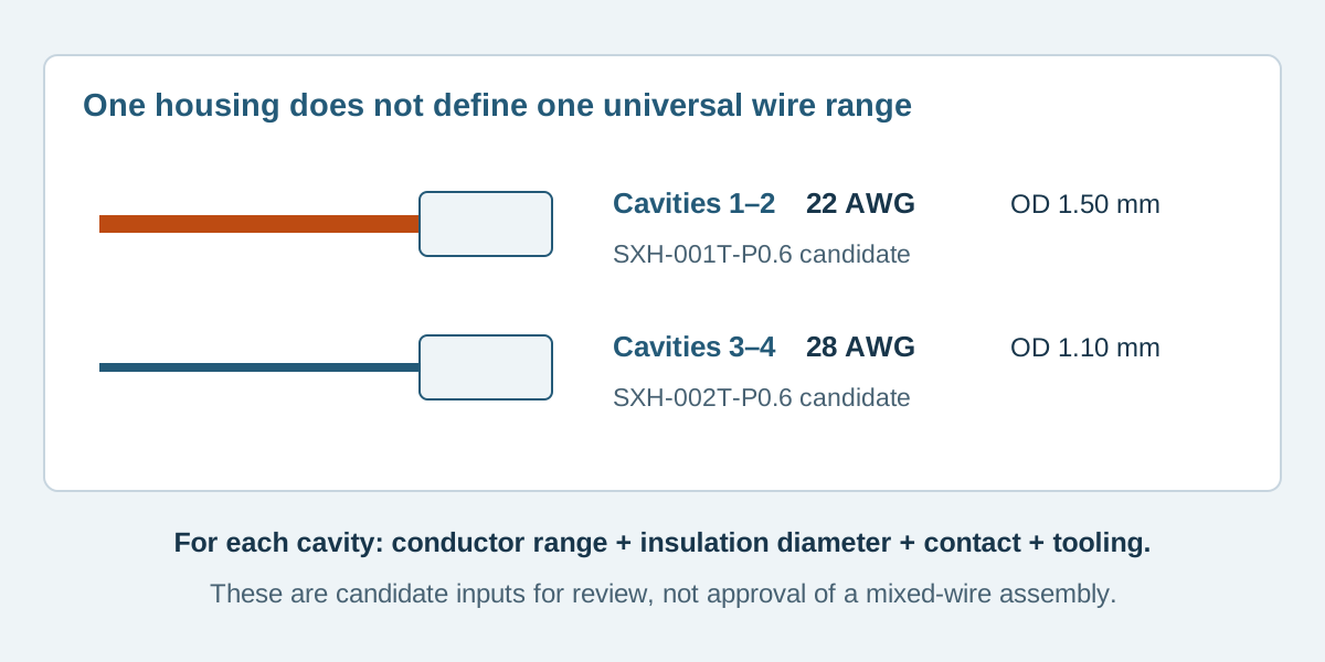
Conceptual illustration. Fictional examples are not approved product configurations, tooling instructions or inspection results.
Start with a cavity schedule
Use the approved housing view to identify each cavity. Add the circuit identity, wire reference, conductor size and insulation outside diameter before choosing a contact. A color name or nominal AWG alone is insufficient to define the wire construction.
Keep one conductor per contact unless the exact contact and application instructions permit the proposed multiple-wire termination. Combining two small wires to imitate a larger conductor is a different construction and needs separate applicability evidence.
Scroll sideways to read all columns.
| Cavity record | Information to capture | Why it remains a separate check |
|---|---|---|
| Wire identity | Full specification, conductor construction and nominal size | The same AWG can describe different constructions |
| Insulation | Material, relevant dimensions and tolerance | The insulation support must suit the actual wire |
| Contact | Complete reference, including suffix | A family range may combine several contact options |
| Housing and mate | Exact references and numbered views | A similar contact outline does not establish system compatibility |
| Process | Applicable tooling and preparation instructions | Sharing a housing does not establish one process setup |
| Application | Required circuit conditions and installed support | Wire fit alone does not establish operating performance |
The wire gauge selection guide addresses voltage drop and the wider current path. This review starts with the proposed wire choices and asks whether their terminations can be specified without ambiguity.
Compare exact contact ranges, not a family headline
The current JST XH catalog, Contact table provides a useful document-reading example:
Scroll sideways to read all columns.
| Contact reference | Catalog conductor range | Catalog insulation outside diameter |
|---|---|---|
| SXH-001T-P0.6 | AWG 28–22 | 0.9–1.9 mm |
| SXH-002T-P0.6 | AWG 30–26 | 0.9–1.3 mm |
These rows identify different selection boundaries. Neither row alone authorizes a finished mixed-gauge assembly. Confirm the exact housing, mating arrangement, applicable wire construction and manufacturing requirements through the relevant product documents and supplier review.
Suffixes also matter. The catalog separately identifies SXH-001T-P0.6N and describes a different contact characteristic; do not shorten both references to “SXH-001” in a BOM. This example does not specify that alternative.
JST's handling precautions direct users to confirm wire compatibility with the chosen crimp terminal and use the relevant connector and tooling instructions. A range check is one input to that review, not its final approval.
A fictional four-cavity screening record
EX-MG-04 is an invented review exercise. It considers an XHP-4 housing candidate with two wire types: W-A, nominal 22 AWG with insulation outside diameter specified as 1.50 ± 0.05 mm; and W-B, nominal 28 AWG with insulation outside diameter 1.10 ± 0.05 mm. W-A and W-B are fictional codes, not purchased wire specifications.
Scroll sideways to read all columns.
| Cavity | Wire candidate | Contact candidate | Initial range screening |
|---|---|---|---|
| 1 | W-A: 22 AWG, 1.50 ± 0.05 mm | SXH-001T-P0.6 | Listed size and insulation range accommodate the stated nominal construction dimensions |
| 2 | W-A: 22 AWG, 1.50 ± 0.05 mm | SXH-001T-P0.6 | Same candidate combination; retain its own circuit identity |
| 3 | W-B: 28 AWG, 1.10 ± 0.05 mm | SXH-002T-P0.6 | Listed size and insulation range accommodate the stated nominal construction dimensions |
| 4 | W-B: 28 AWG, 1.10 ± 0.05 mm | SXH-002T-P0.6 | Same candidate combination; retain its own circuit identity |
The full stated diameter intervals, 1.45–1.55 mm and 1.05–1.15 mm, lie within their candidate rows. That arithmetic does not establish crimp quality, system approval or a current rating. Wire construction, actual documentation, housing/contact applicability, tooling, inspection and intended conditions remain open until reviewed.
For example, changing W-B to a 1.40 mm insulation diameter would move it outside the stated SXH-002T-P0.6 range, even if it remained 28 AWG. Do not solve that conflict by squeezing the insulation, removing strands or silently changing a contact. Record a revised candidate and repeat the affected review.
Keep separate process combinations identifiable
Ask the proposed manufacturer to identify the applicable tooling and process documentation for each contact-wire combination. Do not assume that contacts fitting the same housing use identical strip lengths, crimp settings or inspection limits.
Use separate rows for the evidence requested: combination identity, relevant document revision, inspection characteristic, acceptance reference and result. The crimp inspection evidence guide explains why one pull result or photograph cannot answer every termination question.
Prevent production records from merging the candidates into “four XH contacts.” The BOM and cavity schedule must preserve which reference belongs on each wire. Where wires have similar colors, agree an identification method that supports the actual assembly and receiving workflow.
Review the assembled cable beyond cavity fit
Mixed wire stiffness can affect how the bundle bends and how installation loads reach the connector. Review the installed route, available slack and restraint for the actual construction. A thicker wire does not automatically provide suitable strain relief for its thinner neighbors.
Check circuit requirements independently. The contact range table above deliberately omits a current claim. Do not transfer a family headline current to every wire size or infer a combined housing rating by adding cavity values. The JST wire gauge and current guide explains the need to retain the conditions attached to ratings.
For a sealed system, add the selected wire-seal and cavity-seal requirements to the matrix. The unsealed XH teaching example does not establish seal compatibility. An unbranded alternative also needs evidence for its own contact, wire and housing combination; original-brand specifications do not automatically transfer.
Mixed-gauge questions
Does one housing require all wires to have the same gauge?
No universal rule follows from the housing alone. Determine which contacts and wires the selected system permits, then obtain approval of the proposed complete construction. Do not infer permission for any mixture from one catalog range.
Can one contact reference cover two different wire sizes?
It may, if both complete wire constructions meet its applicable requirements. Record and review each contact-wire combination rather than treating a shared contact reference as proof that both process setups are equivalent.
Does passing the diameter and AWG check approve the assembly?
No. It is an initial screen. Exact component applicability, wire construction, process evidence, operating conditions and customer approval still need resolution.
Request review of the complete cavity schedule
Contact Zeakka with the housing and mate references, numbered cavity view, each wire specification and proposed contact rows. Include the intended circuit conditions and required evidence. Zeakka coordinates sourcing as a trading partner; any mixed-gauge construction remains subject to project-specific review. Original JST or Molex components are considered only inside confirmed finished assemblies, not offered as loose original parts.
Share this article
Help others discover this content